
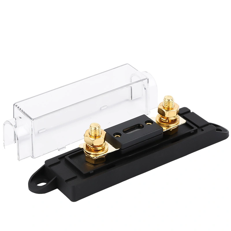
Wiring a DC fuse holder looks like the simplest job on the panel: two terminals, two cables, tighten and go. It is also where a surprising number of commissioning problems originate, because in DC the questions that matter — which side is the supply, which side is the load, and what the manufacturer's marking actually means — have consequences that do not exist on the AC side. This article covers what polarity and direction really mean in a DC holder, what goes wrong when they are ignored, and how to wire the assembly so it stays reliable.
What Polarity Means in a DC Holder
Start with a clarification that saves a lot of confusion. The fuse link itself is, in most designs, a symmetrical thermal device: it responds to current regardless of direction. What is directional is the assembly around it. Some DC holders and some DC-rated links carry explicit polarity or line-side markings. Where they exist, they reflect real design features — an arc-management geometry that assumes a particular current direction, a shielded or partitioned terminal arrangement, an indicator or striker circuit that is polarity sensitive, or simply the manufacturer's tested configuration. When a marking exists, it is not decorative. It defines the configuration the device was type-tested in, and following it is the only way to be sure the published DC performance applies. Where no marking exists, the more important concept is not polarity but position.
Line Side and Load Side Matter More Than You Think
In a DC circuit, the protective device should be installed as close to the source as practicable, with the supply connected to the line side and the downstream equipment to the load side. The reason is straightforward. Once the device operates, everything on the load side is disconnected from the source. Everything on the line side remains energised. If the assembly is wired the other way round, opening the device still stops the fault, but the fuse holder and its terminals stay live — which is precisely the situation you do not want when someone opens the enclosure to investigate. This applies whether the source is a battery bank, a PV array, or a rectifier. In a PV system, for example, the array is a source: the string side is the line side, and the inverter side is the load side, even though current flows from array to inverter.
What Actually Happens When It Is Wired Backwards
Three consequences are worth naming. First, safety during service. As above, the wrong arrangement leaves exposed terminals energised after operation, and an enclosure that looks de-energised but is not. Second, tested performance. A holder with a defined current path and arc management geometry was type-tested in one configuration. Reversing it may not invalidate the interruption — the link may still clear — but you are now operating outside the configuration the certification covers. Third, indicator and monitoring circuits. Any holder or link fitted with an indicator, striker pin, or microswitch may be polarity dependent. Wired backwards, the indication simply fails to work, and a blown device looks healthy.
Choose the Holder Before You Choose the Cable
A large share of wiring problems are created before anyone strips a cable, by specifying the holder last. Decide these first:
- Voltage rating, matched to the maximum system voltage including cold-temperature rise for solar or maximum state of charge for batteries
- Current rating, derated for the actual enclosure temperature
- The fuse body size and format the circuit requires
- Terminal type — screw, stud, spade, or crimp — matched to the cable you intend to use
- Ingress protection appropriate to the location
- Whether the assembly needs an indicator, and whether that indicator is polarity sensitive
Selecting the holder to match the cable, rather than the cable to match the holder, is what leads to adapters, stacked lugs, and marginal terminations.
Termination Method Decides Reliability
Most DC holder failures start at the termination, not in the holder body. Use crimped lugs sized for both the cable cross-section and the terminal stud. Crimp with the correct die, not with pliers or a generic tool. Support the cable so that its weight and any vibration are not carried by the terminal, and provide a service loop so the conductor can be re-terminated once without being shortened. Tighten to the manufacturer's specified torque with a calibrated tool, and re-check after the first thermal cycle. A joint that is correctly made stays cool; one that is not will announce itself within weeks. Avoid tinned copper conductors in screw terminals without the correct ferrule, because solder creeps under pressure and the joint loosens over time.
Ingress Protection Is Part of the Wiring Job
A holder is only as well sealed as the cable entry that serves it. If the enclosure is rated IP65 or better, the cable glands, blanking plugs, and the holder's own sealing arrangement all have to meet that rating. A single unsealed entry turns a sealed enclosure into a condensation trap, and moisture at a DC terminal produces corrosion, resistance, and eventually heat. For outdoor solar work, confirm UV resistance of the holder body and any exposed gasketing, and route cables so that water does not track along them into the enclosure.
A Wiring Sequence That Holds Up
Work in this order:
- Identify the source and confirm which side is line and which is load
- Check the holder and link for polarity or line-side markings and follow them
- Select the cable cross-section for the current and the run length, and fit correctly crimped terminations
- Route and support the cable so no mechanical load reaches the terminal
- Fit the holder, observing the specified ingress protection at every entry
- Tighten to the specified torque, in stages, with a calibrated tool
- Label both sides clearly so the next person does not have to work it out
- Verify with a millivolt drop check under load and an infrared scan at commissioning
That last step takes minutes and catches almost every wiring error before it becomes a service call.
Summary
Polarity markings on a DC holder are not decorative — they define the tested configuration. Line and load orientation determines whether the assembly is safe to work on after it operates. And the reliability of the whole installation is decided at the terminations, by correct crimp tooling, correct torque, and sealing that matches the enclosure rating.
About Our DC Holder Range
GFEFUSE is the brand of Dongguan Gongfu Electronics Co., Ltd., an electronic protection device manufacturer established in Dongguan, Guangdong in 2013. Our integrated development, production, and sales team operates five advanced production lines with thirteen R&D engineers, and our products are exported to customers overseas. Our fuse holder range covers inline, panel, and bolted configurations for DC work, including panel fuse holder options for enclosure mounting and bolt fuse holder options for high-current busbar connections. Solar installations typically pair these with our photovoltaic fuse range so the link and holder are verified as a set. Products carry UL, cULus, TUV, CE, and CQC certification and comply with RoHS and REACH directives, serving new energy, power equipment, automotive electronics, communication systems, and consumer electronics.
Conclusion
Two terminals, but four decisions: which side is the source, what the markings require, how the cable is terminated, and how the enclosure stays sealed. Get those right and a DC fuse holder will sit in service for years without attention. Get them wrong and the failure will look, months later, like a defective part.
Send us your system voltage, current, cable size, and enclosure rating. We will confirm the right holder, the termination method, and the matching link.
Frequently Asked Questions
Practical answers on wiring DC holders correctly.
Does a DC fuse holder have polarity?
Sometimes. Some DC holders and links carry line-side or polarity markings reflecting their tested configuration, an indicator circuit, or a specific arc-management geometry. Where a marking exists, follow it. Where none exists, the line and load orientation is the critical decision.
What happens if I wire a DC fuse holder backwards?
The device will usually still interrupt the fault, but the holder terminals may remain energised after operation, any indicator circuit may not work, and you may be operating outside the tested configuration. It is a safety and compliance issue rather than a performance one.
Which side should the supply connect to?
The line side, with the load on the other. In a PV system the array is the source, so the string side is the line side. In a battery system the battery is the source. Always install the device as close to the source as practicable.
How do I stop the terminals loosening over time?
Use correctly crimped lugs with the right die, tighten to the manufacturer's torque with a calibrated tool, support the cable so no weight or vibration reaches the terminal, and re-check torque after the first thermal cycle.
Does the enclosure rating matter for the holder?
Yes. The holder and every cable entry must meet the enclosure's ingress rating. One unsealed entry creates a condensation path, and moisture at a DC terminal leads to corrosion, rising resistance, and heat.